Difference between revisions of "Network router"
(→First stage) |
|||
| Line 21: | Line 21: | ||
== First stage == | == First stage == | ||
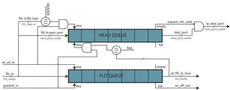
| − | Each input port manages a separate buffering for each virtual channel. An incoming flit | + | Each input port manages a separate buffering for each virtual channel. An incoming flit carries the virtual channel ID in which it have to be enqueued. The implementation for a single virtual channel is reported below. |
[[File:first_stage.jpg|1000px|Router first stage]] | [[File:first_stage.jpg|1000px|Router first stage]] | ||
Latest revision as of 12:34, 2 July 2019
This section describes the Router implementation.
The router is part of a mesh network, it has an I/O port for each cardinal direction, plus the local injection/ejection port.
Each port exchanges FLITs with neighbour routers. FLITs are routed using the XY-DOR protocol with look-ahead. This means every router calculates the next hop as if it were the next router along the path. This optimization allows us to reduce the pipeline length of the router, improving latencies.
For coherence-related reasons, the network has four virtual channels, each classifies different packet types. Furthermore, an On/Off back-pressure for each virtual channel avoids FIFOs overflow. The following rules must be ensured:
- a flit cannot be routed on a different virtual channel;
- different packets cannot be interleaved on the same virtual channel;
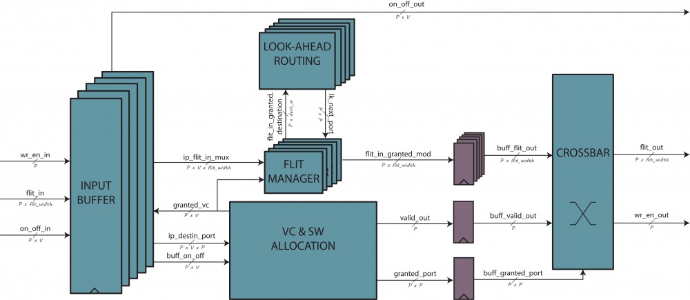
The router is implemented in a pipelined fashion. Although three stages are presented, the last one's output is not buffered. This effectively reduces the pipeline delay to two stages.
The first stage consists of input buffers, connected directly to the input ports. They are responsible for the storage of flits to be routed and for the generation of the back-pressure signals.
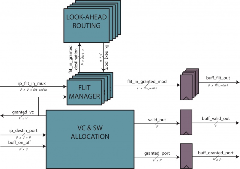
The second stage is composed of three main blocks: the allocator, the flit manager and the routing logic. The allocator manages the allocation of the third stage ports, generating a grant signal for each virtual channel allowed to proceed, considering also back-pressure signals coming from other routers. This grant is used by the flit manager to select the winning flits, which are fed to the next stage along with the routing information generated by the routing block.
The third stage is a cross-bar, allowing each of the 5 input port to access each of the 5 output port, provided that no collisions are found.
Contents
First stage
Each input port manages a separate buffering for each virtual channel. An incoming flit carries the virtual channel ID in which it have to be enqueued. The implementation for a single virtual channel is reported below.
For each virtual channel, two FIFO buffers are used: a general flit queue, which must enqueue every incoming flit, and a head queue, responsible of storing only the output port of each incoming flit. The queues have the same capacity, to account the worst case, that is, the presence of only head-tail flits.
So the general flit queue will enqueue every incoming flit and will dequeue one as soon as the allocator grants it permission. The head queue will enqueue every incoming head or head-tail flit and will dequeue one as soon as a tail or head-tail flit gets dequeued from the general flit queue.
The number of flits stored in the buffers is used to generate the back-pressure signals. In particular, we should guarantee that the system is packet loss-free while generating those signals. As there is one pipeline stage delay between these buffers and the previous router's allocator, we must raise the On/Off signal when the buffer has one free slot.
FIFO instantiation code is reported below.
genvar                                            i;
generate
	for( i=0; i < `VC_PER_PORT; i=i + 1 ) begin : vc_loop
		sync_fifo #(
			.WIDTH ( $bits( flit_t )   ),
			.SIZE  ( `QUEUE_LEN_PER_VC ),
			.ALMOST_FULL_THRESHOLD ( `QUEUE_LEN_PER_VC - 1 ) )
		flit_fifo (
			.clk         ( clk                           ),
			.reset       ( reset                         ),
			.flush_en    (                               ),
			.full        (                               ),
			.almost_full ( on_off_out[i]                 ),
			.enqueue_en  ( wr_en_in & flit_in.vc_id == i ),
			.value_i     ( flit_in                       ),
			.empty       ( ip_empty[i]                   ),
			.almost_empty(                               ),
			.dequeue_en  ( sa_grant[i]                   ),
			.value_o     ( ip_flit_in_mux[i]             )
		);

		sync_fifo #(
			.WIDTH ( $bits( port_t ) ),
			.SIZE ( `QUEUE_LEN_PER_VC ) )
		header_fifo (
			.clk         ( clk                                                                                       ),
			.reset       ( reset                                                                                     ),
			.flush_en    (                                                                                           ),
			.full        (                                                                                           ),
			.almost_full (                                                                                           ),
			.enqueue_en  ( wr_en_in & flit_in.vc_id == i & ( flit_in.flit_type == HEADER | flit_in.flit_type == HT ) ),
			.value_i     ( flit_in.next_hop_port                                                                     ),
			.empty       ( request_not_valid[i]                                                                      ),
			.almost_empty(                                                                                           ),
			.dequeue_en  ( ( ip_flit_in_mux[i].flit_type == TAIL | ip_flit_in_mux[i].flit_type == HT ) & sa_grant[i] ),
			.value_o     ( dest_port_app                                                                             )
		);
As stated before, this will work as long as packets don't interleave on the same virtual channel.
Second stage
The second stage takes as input requests coming from each virtual channel, along with back-pressure signals sent by other routers. Its main goals are:
- allocate resources, which in this case are crossbar input ports;
- properly update the routing information for each flits passing through.
The overall implementation is reported below.
Grant signals are also fed-back to the first stage, to allow flits to be dequeued.
Look-ahead routing logic is replicated for each input port. This way, as soon as we know which virtual channel has been granted access for each input port, we can calculate the routing information.
Allocator implementation
The allocator is required, as we have a request for every virtual channel storing valid flits, each requiring access to an output port. As the third stage has only five input ports, and only one is allowed to access a given output port, requests must be scheduled.
The allocator can be decomposed in two parts:
- virtual channel allocator, which ensures that for every output virtual channel only one input virtual channel is granted access to it;
- switch allocator, which first ensures that for every input port there is only one virtual channel allowed to access the crossbar, and then ensures that for every output port there is only one input port allowed to access the crossbar.
Virtual channel allocator
Virtual channel allocation is implemented using a round-robin arbiter, with additional grant-and-hold circuitry (as implemented by the allocator core module). Once an input virtual channel has been granted access to an output virtual channel, the grant will be held until its request is fulfilled. This is to ensure that multiple packets do not interleave on the same virtual channel.
Back-pressure signals from other routers are used in this stage.
The output grant signals are generated on a virtual-channel basis and fed to the next stage.
Switch allocator
The switch allocator has two roles:
- it chooses, for each port's candidate virtual channels, which one is granted access;
- it chooses, if there are any input ports requesting access to the same output port, which one is granted access.
The first part is implemented using a round-robin arbiter, allowing flits coming from different virtual channels to be interleaved on the same output port, as the first stage has already ensured that no two virtual channels have been granted access to the same output virtual channel.
generate
	for( i=0; i < `PORT_NUM; i=i + 1 ) begin : sw_allocation_loop

		assign va_grant_per_port[i] = {`PORT_NUM{| ( va_grant[i] & ~ip_empty[i] )}};

		rr_arbiter #(
			.NUM_REQUESTERS( `VC_PER_PORT ) )
		sa_arbiter (
			.clk       ( clk                               ),
			.reset     ( reset                             ),
			.request   ( va_grant[i] & ~ip_empty[i] ),
			.update_lru( 1'b1                              ),
			.grant_oh  ( grant_to_mux_ip[i]                )
		);

		mux_npu #(
			.N    ( `VC_PER_PORT ),
			.WIDTH( `PORT_NUM    )
		)
		sa_mux (
			.onehot( grant_to_mux_ip[i] ),
			.i_data( ip_dest_port[i]    ),
			.o_data( sa_port[i]         )
		);
	end
endgenerate
At this point, we can proceed with the second part, and we also have all the required information to perform the routing calculation. In fact, we know for each input port which virtual channel has been granted access.
The second part is implemented again with a round-robin arbiter and a grant-and-hold circuitry, using the allocator core. It guarantees that now we have no conflicts on switch allocation, and we can use this grant signals to set up the crossbar.
Allocator core
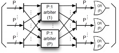
The allocator core is a generic round-robin allocator, composed of a parameterizable number of parallel arbiters in which the input and output are properly scrambled and the output are or-ed to obtain the grant signals.
module allocator_core #(
		parameter N    = 5,  // input ports
		parameter M    = 4,  // virtual channels per port
		parameter SIZE = 5 ) // output ports
	(
		input                                             clk,
		input                                             reset,
		input  logic [N - 1 : 0][M - 1 : 0][SIZE - 1 : 0] request,
		input  logic [N - 1 : 0][M - 1 : 0]               on_off,
		output logic [N - 1 : 0][M - 1 : 0]               grant
	);
It also provides a grant-and-hold circuitry.
Look-ahead routing
The look-ahead routing calculates the output port as if it were the next router on the path. This allows to do it in parallel with the switch allocator, as the switch allocator doesn't need the routing output. Otherwise, an additional pipeline stage for routing calculation would be needed.
Flit manager
The flit manager selects, for each port, the flit which has access to the crossbar inputs. It also modifies the flit to include the routing results.
for( i=0; i < `PORT_NUM; i=i + 1 ) begin : flit_loop
	always_comb begin
		flit_in_granted_mod[i] = flit_in_granted[i];
			if ( flit_in_granted[i].flit_type == HEADER || flit_in_granted[i].flit_type == HT )
				flit_in_granted_mod[i].next_hop_port = port_t'( lk_next_port[i] );
end
Third stage
The third stage is a crossbar, connecting 5 input ports to respectively 5 output ports.
It has been implemented as a mux for each output port, and selection signals are obtained from the second stage outputs.
The output of this stage is not buffered. This means that in practice, the clock cycles needed to completely process a packet reduce to two.


