Difference between revisions of "Network"
(→vn_net2core) |
(→First stage) |
||
| Line 118: | Line 118: | ||
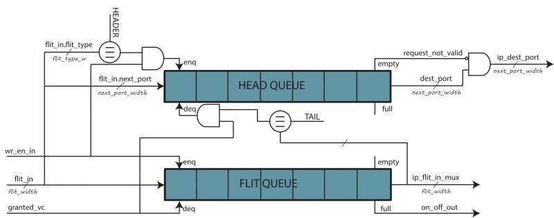
There are two queues: one to house flits (FQ) and another to house only head flits (HQ). The queue lengths are equals to contemplate the worst case - packets with only one flit. Every time a valid flit enters in this unit, the HQ enqueues its only if the flit type is `head' or `head-tail'. The FQ has the task of housing all the flits, while the HQ has to "register" all the entrance packets. To assert the dequeue signal for HQ, either allocator grant assertion and the output of a tail flit have to happen, so the number of elements in the HQ determines the number of packet entered in this virtual channel. | There are two queues: one to house flits (FQ) and another to house only head flits (HQ). The queue lengths are equals to contemplate the worst case - packets with only one flit. Every time a valid flit enters in this unit, the HQ enqueues its only if the flit type is `head' or `head-tail'. The FQ has the task of housing all the flits, while the HQ has to "register" all the entrance packets. To assert the dequeue signal for HQ, either allocator grant assertion and the output of a tail flit have to happen, so the number of elements in the HQ determines the number of packet entered in this virtual channel. | ||
| + | |||
| + | header_fifo ( | ||
| + | .enqueue_en ( wr_en_in & flit_in.vc_id == i & ( flit_in.flit_type == HEADER | flit_in.flit_type == HT ) ), | ||
| + | .value_i ( flit_in.next_hop_port ), | ||
| + | .dequeue_en ( ( ip_flit_in_mux[i].flit_type == TAIL | ip_flit_in_mux[i].flit_type == HT ) & sa_grant[i] ), | ||
| + | ... | ||
| + | ... | ||
This organization works only if a condition is respected: the flits of each packets are stored consecutively and ordered in the FQ. To obtain this condition, a deterministic routing has to be used and all the network interfaces have to send all the flits of a packet without interleaving with other packet flits. | This organization works only if a condition is respected: the flits of each packets are stored consecutively and ordered in the FQ. To obtain this condition, a deterministic routing has to be used and all the network interfaces have to send all the flits of a packet without interleaving with other packet flits. | ||
Revision as of 17:15, 21 September 2017
The many-core system relies on an interconnection network in order to exchange the coherence, synchronization and boot messages. An interconnection network is a programmable system that moves data between two or more terminals. A network-on-chip is an interconnection network connecting microarchitectural components. Out NoC choice is a 2D mesh. A mesh is a segmented bus in two dimensions with added complexity to route data across dimensions.
It is explained how the network-on-chip is designed and created. A packet from a source has to be: (1) injected/ejected in/from the network system, (2) routed to the destination over specific wires. The first operation is done by the Network interface, the second from the Router.
In order to have a scalable system, each tile has its own Router and Network Interface.
Contents
Network Interface
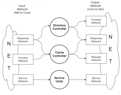
The Network Interface is the "glue" that merge all the component inside a tile that want to communicate with other tile in the NoC. It has several interface with the element inside the tile and an interface with the router. Basically, it has to convert a packet from the tile into flit injected in to the network and viceversa. In order to avoid deadlock, four different virtual network are used: request, forwaded request, response and service network.
The interface to the tile communicate with directory controller, cache controller and service units (boot manager, barrier core unit, synchronization manager). The units use the VN in this way:
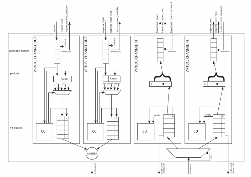
The unit is divided in two parts:
- TO router, in which the vn_core2net units buffer and convert the packet in flit;
- FROM router, in which the vn_net2core units buffer and convert the flit in packet.
These two units support the multicast, sending k times a packet in unicast as many as the destinations are.
The vn_net2core units should be four as well as vn_core2net units, but the response network is linked with the DC and CC at the same time. So the solution is to add another vn_net2core and vn_core2net unit with the same output of the other one. If the output of the NI contains two different output port - so an output arbiter is useless, the two vn_core2net response units, firstly, has to compete among them and, secondly, among all the VN.
Note that packet_body_size is linked with the flit_numb, but we prefer to calculate them separately. (FILT_NUM = ceil(PACKET_BODY/FLIT_PAYLOAD) )
vn_net2core
This module stores incoming flit from the network and rebuilt the original packet. Also, it handles back-pressure informations (credit on/off). A flit is formed by an header and a body, the header has two fields: |TYPE|VCID|. VCID is fixed by the virtual channel ID where the flit is sent. The virtual channel depends on the type of message. The filed TYPE can be: HEAD, BODY, TAIL or HT. It is used by the control units to handles different flits.
When the control unit checks the TAIL or HT header, the packet is complete and stored in packed FIFO output directly connected to the Cache Controller.
E.g. : If those flit sequence occurs:
         1st Flit in => {FLIT_TYPE_HEAD, FLIT_BODY_SIZE'h20}
         2nd Flit in => {FLIT_TYPE_BODY, FLIT_BODY_SIZE'h40}
         3rd Flit in => {FLIT_TYPE_BODY, FLIT_BODY_SIZE'h60}
         4th Flit in => {FLIT_TYPE_TAIL, FLIT_BODY_SIZE'h10};
The rebuilt packet passed to the Cache Controller is:
Packet out => {FLIT_BODY_SIZE'h10, FLIT_BODY_SIZE'h60, FLIT_BODY_SIZE'h40, FLIT_BODY_SIZE'h20}
A FIFO stores the reconstructed packet. When the CC can read, it asserts packet_consumed bit.
The FIFO threshold is reduced of 2 due to controller: if a sequence of consecutive 1-flit packet arrives, the on-off backpressure almost_full signal will raise up the clock edge after the threshold crossing as usual, so it is important to reduce of 2 the threshold to avoid packet lost. If the packet arriving near the threshold are bigger than 1 flit, the enqueue will be stopped with 1 free buffer space.
Control unit
Flits from the network are not stored in any FIFOs. The router_valid signal is directly connected to the rebuilt packet control unit. In Control Unit all incoming flit are mounted in a packet. It checks the Flit header, if it is a TAIL or a HT type, the control unit stores the composed packet in the output FIFO to the Cache Controller.
vn_core2net
This module stores the original packet and converts in flit for the network. The conversion in flit starts fetching the packet from an internal queue. When the requestor has to send a packet, it asserts packed_valid bit, directly connected to the FIFO enqueue_en port. Those informations are used by the Control Unit to translate packet in FLITs for each destination.
Control unit
The Control Unit strips the packet from the Cache Controller into N flits for the next router. It checks the packet_has_data field, if a packet does not contain data, the CU generates just a flit (HT type), otherwise it generates N flits. It supports multicasting through multiple unicast messages.
A priority encoder selects from a mask which destination has to be served. All the information of the header flit are straightway filled, but the flit type.
assign packet_dest_pending = packet_destinations_valid & ~dest_served;
rr_arbiter # (
   .NUM_REQUESTERS ( DEST_NUMB )
)
rr_arbiter (
   .clk        ( clk                  ) ,
   .reset      ( reset                ) ,
   .request    ( packet_dest_pending  ) ,
   .update_lru ( 1'b0                 ) ,
   .grant_oh   ( destination_grant_oh )
) ;
The units performs the multicast throughout k unicast: when a destination is served (a packet is completed), the corresponding bit in the destination mask is deasserted.
dest_served <= dest_served | destination_grant_oh;
The units has to know if the multicast is on. In this case, the signal packet_destinations_valid is a bitmap of destination to reach and the real_dest has the TILE_COUNT width; else the signal real_dest contains the (x,y) coordinates of the destination
generate
   if ( DEST_OH == "TRUE" ) begin
      assign
         real_dest.x  = destination_grant_id[`TOT_X_NODE_W - 1 : 0 ],
         real_dest.y  = destination_grant_id[`TOT_Y_NODE_W + `TOT_X_NODE_W - 1 -: `TOT_X_NODE_W];
   end else
      assign real_dest = packet_destinations[destination_grant_id];
endgenerate
Note: if DEST_OH is false, the core_destination signal contains the component ID inside the tile that will receive the packet, else it has no sense.
assign cu_flit_out_header.core_destination = tile_destination_t'( destination_grant_oh[`DEST_TILE_W -1 : 0] );
Router
The router moves data between two or more terminals, so the interface is standard: input and output flit, input and output write enable, and backpressure signals.
This is a virtual-channel flow control X-Y look-ahead router for a 2D-mesh topology.
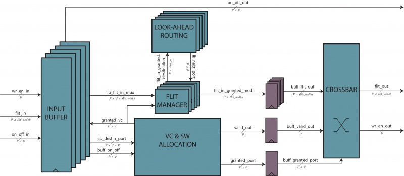
The first choice is to use only input buffering, so this will take one pipe stage. Another technique widely used is the look-ahead routing, that permits the route calculation of the next node. It is possible to merge the virtual channel and switch allocation in just one stage.
Recapping, there are 4 stages, two of them working in parallel (routing and allocation stages), for a total of three stages. To further reduce the pipeline stages, the crossbar and link traversal stage is not buffered, reducing the stages at two and, de facto, merging the last stage to the first one.
First stage
There will be five different port - cardinal directions plus local port -, each one with V different queues, where V is the number of virtual channels presented.
There are two queues: one to house flits (FQ) and another to house only head flits (HQ). The queue lengths are equals to contemplate the worst case - packets with only one flit. Every time a valid flit enters in this unit, the HQ enqueues its only if the flit type is `head' or `head-tail'. The FQ has the task of housing all the flits, while the HQ has to "register" all the entrance packets. To assert the dequeue signal for HQ, either allocator grant assertion and the output of a tail flit have to happen, so the number of elements in the HQ determines the number of packet entered in this virtual channel.
header_fifo (
   .enqueue_en  ( wr_en_in & flit_in.vc_id == i & ( flit_in.flit_type == HEADER | flit_in.flit_type == HT ) ),
   .value_i     ( flit_in.next_hop_port                                                                     ),
   .dequeue_en  ( ( ip_flit_in_mux[i].flit_type == TAIL | ip_flit_in_mux[i].flit_type == HT ) & sa_grant[i] ),
   ...
   ...
This organization works only if a condition is respected: the flits of each packets are stored consecutively and ordered in the FQ. To obtain this condition, a deterministic routing has to be used and all the network interfaces have to send all the flits of a packet without interleaving with other packet flits.
Second stage
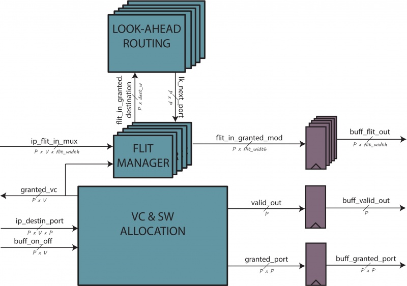
The second stage has got two units working in parallel: the look-ahead routing unit and allocator unit. This two units are linked throughout a intermediate logic. The allocator unit has to accord a grant for each port. This signal is feedback either to first stage and to a second-stage multiplexer as selector signal. This mux receives as input all the virtual channel output for that port, electing as output only one flit - based on the selection signal. This output flit goes in the look-ahead routing to calculate the next-hop port destination.
Allocation
The allocation unit grants a flit to go toward a specific port of a specific virtual channel, handling the contention of virtual channels and crossbar ports. Each single allocator is a two-stage input-first separable allocator that permits a reduced number of component respect to other allocator.
The overall unit receives as many allocation request as the ports are. Each request asks to obtain a destination port grant for each of its own virtual channel - the total number of request lines is P x V x P. The allocation outputs are two for each port: (1) the winner destination port that will go into the crossbar selection; (2) the winner virtual channel that is feedback to move the proper flit at the crossbar input.
The allocation unit has to respect the following rules:
- the packets can move only in their respective virtual channel;
- a virtual channel can request only one port per time;
- the physical link can be interleaved by flits belonging to different flows;
- when a packet acquires a virtual channel on an output port, no other packets on different input ports can acquire that virtual channel on that output port.
Virtual channel allocation
The first step for the virtual channel allocator is removed because the hypothesis is that only one port per time can be requested for each virtual channel. Under this condition, a first-stage arbitration is useless, so only the second stage is implemented.
The use of grant-hold arbiters in the second stage avoids that a packet loses its grant when other requests arrive after this grant. The on-off input signal is properly used to avoid that a flit is send to a full virtual channel in the next node.
Switch allocation
The switch allocator receives as input the output signals from VC allocation and all the port requests. For each port, there is a signal assertion for each winning virtual channel. These winners now compete for a switch allocation. Two arbiter stage are necessary. The first stage arbiter has as many round-robin arbiter as the input port are. Each round-robin arbiter chooses one VC per port and uses this result to select the request port associated at this winning VC. The winning request port goes at the input of second stage arbiter as well as the winning requests for the other ports. The second stage arbiter is an instantiation of the allocator core and chooses what input port can access to the physical links. This signal is important for two reasons: (1) it is moved toward the round-robin unit previously and-ed with the winning VC for each port; (2) it is registered, and-ed with the winning destination port, and used as selection port for the crossbar (for each port).
Flit handler
A mux uses the granted_vc signal to grant one of the input flit to the output register. This flit then will goes to the input crossbar port.
Next hop routing calculation
The look-ahead routing calculates the destination port of the next node instead of the actual one because the actual destination port is yet ready in the header flit. The algorithm is a version of the X-Y deterministic routing. It is deadlock-free because it removes four on eight possible turns: when a packet turns towards Y directions, it cannot turn more.
