Network
The many-core system relies on an interconnection network in order to exchange the coherence, synchronization and boot messages. An interconnection network is a programmable system that moves data between two or more terminals. A network-on-chip is an interconnection network connecting microarchitectural components. Out NoC choice is a 2D mesh. A mesh is a segmented bus in two dimensions with added complexity to route data across dimensions.
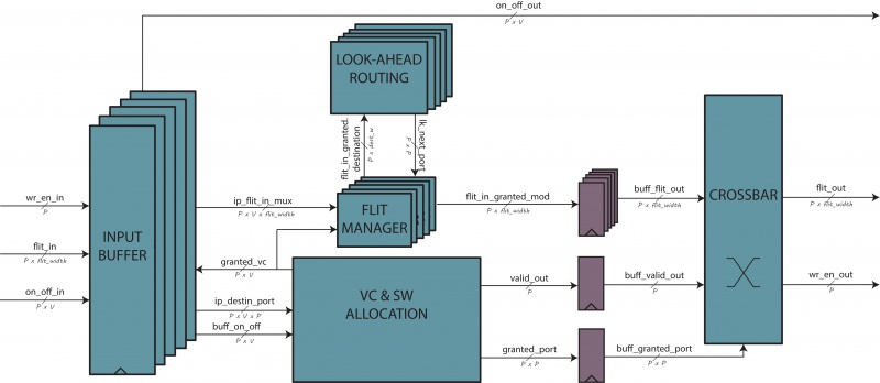
It is explained how the network-on-chip is designed and created. A packet from a source has to: 1- injected/ejected in/from the network system, 2- routed to the destination over specific wires. THe first operation is done by the Network interface, the second from the Router.
In order to have a scalable system, each tile has its own Router and Network Interface.
Network Interface
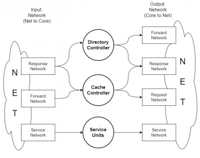
The Network Interface is the "glue" that merge all the component inside a tile that want to communicate with other tile in the NoC. It has several interface with the element inside the tile and an interface with the router. Basically, it has to convert a packet from the tile into flit injected in to the network and viceversa. In order to avoid deadlock, four different virtual network are used: request, forwaded request, response and service network.
The interface to the tile communicate with directory controller, cache controller and service units (boot manager, barrier core unit, synchronization manager). The units use the VN in this way:
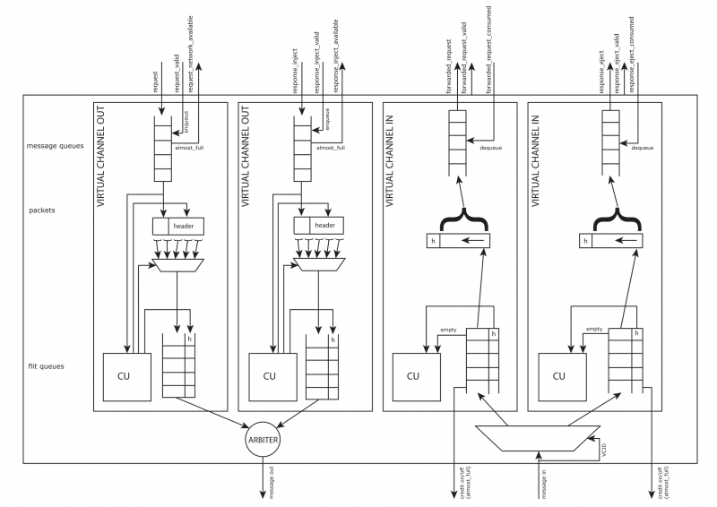
The unit is divided in two parts:
- TO router, in which the vn_core2net units buffer and convert the packet in flit;
- FROM router, in which the vn_net2core units buffer and convert the flit in packet.
These two units support the multicast, sending k times a packet in unicast as many as the destinations are.
The vn_net2core units should be four as well as vn_core2net units, but the response network is linked with the DC and CC at the same time. So the solution is to add another vn_net2core and vn_core2net unit with the same output of the other one. If the output of the NI contains two different output port - so an output arbiter is useless, the two vn_core2net response units, firstly, has to compete among them and, secondly, among all the VN.
Note that packet_body_size is linked with the flit_numb, but we prefer to calculate them separately. (FILT_NUM = ceil(PACKET_BODY/FLIT_PAYLOAD) )
vn_net2core
This module stores incoming flit from the network and rebuilt the original packet. Also, it handles back-pressure informations (credit on/off). A flit is formed by an header and a body, the header has two fields: |TYPE|VCID|. VCID is fixed by the virtual channel ID where the flit is sent. The virtual channel depends on the type of message. The filed TYPE can be: HEAD, BODY, TAIL or HT. It is used by the control units to handles different flits.
When the control unit checks the TAIL or HT header, the packet is complete and stored in packed FIFO output directly connected to the Cache Controller.
E.g. : If those flit sequence occurs:
         1st Flit in => {FLIT_TYPE_HEAD, FLIT_BODY_SIZE'h20}
         2nd Flit in => {FLIT_TYPE_BODY, FLIT_BODY_SIZE'h40}
         3rd Flit in => {FLIT_TYPE_BODY, FLIT_BODY_SIZE'h60}
         4th Flit in => {FLIT_TYPE_TAIL, FLIT_BODY_SIZE'h10};
The rebuilt packet passed to the Cache Controller is:
Packet out => {FLIT_BODY_SIZE'h10, FLIT_BODY_SIZE'h60, FLIT_BODY_SIZE'h40, FLIT_BODY_SIZE'h20}
vn_core2net
Router
The Router bla bla bla bla


